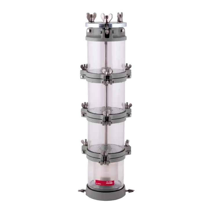
Oil level Indicators
Magnetic Oil Level Indicator (FORM C, D, E)
Form C,D,E Oil Level Indicators are used in transformers of powers greater than 5000 kVA for the purpose of monitoring their oil level. Structurally this product consists of two basic parts; the isolated flange and the indicator. Indicator unit has no contact with the oil. Indicator unit has ventilation holes which are located on the upper and bottom rear sides in order to prevent the accumulation of condensed water. Oil level indicators do not allow oil leakage at temperatures of 110°C, 0,5 bar effective pressure and vacuum.
Indicator unit has no contact with the oil.
Indicator unit has ventilation holes which are located on the upper and bottom rear sides in order to prevent the accumulation of condensed water.
Oil level indicators do not allow oil leakage at temperatures of 110°C, 0,5 bar effective pressure and vacuum.
Isolation Flange: Injected Aluminum Indicator Unit: Injected Aluminum, painted with RAL 7033 or RAL 7001
Indicator Dial: Aluminum sheet, coated with black eloxal and yellow serigraphy
Pointer: Yellow painted brass
Indicator glass: Polycarbonate (UV resistant)
Float: Oil resistant, closed cellular type special plastic foam
Contacts: Switches in compliance with DIN VDE 0660
Outer screws: Stainless steel
KYS FORM C,D,E Level Indicators are manufactured with terminal-box connection option only. Connection diagrams are the same as for FORM B.
Do you have questions about our product, would you like personal advice, or do you want to place an order? Our team is happy to assist you with help and guidance!
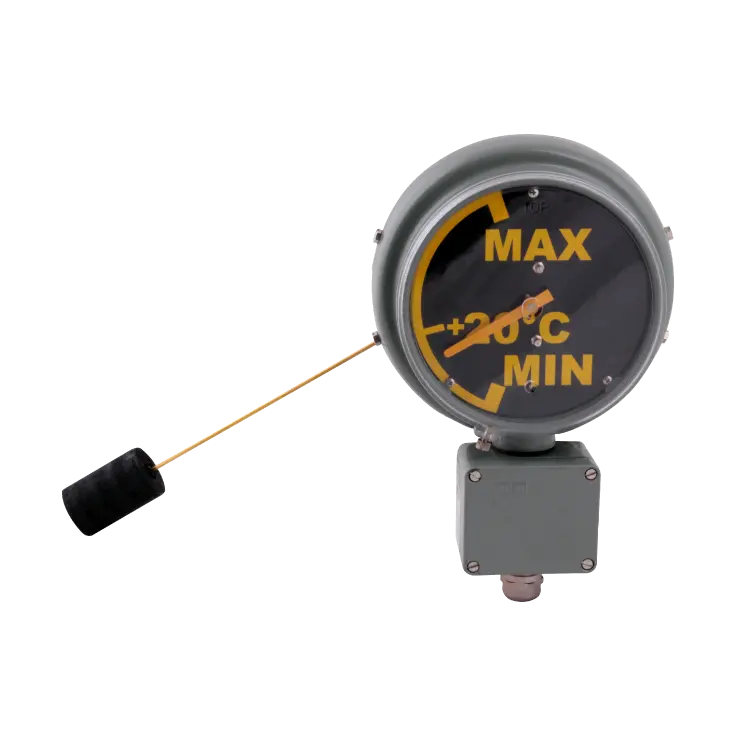
Operation principle
The float movement associated with the oil level is radially transmitted to the magnetic coupling system of the indicator via the float lever. A magnet connected to the float-lever mechanism, drives the polarized indicator magnet connected to the pointer.
If requested, this movement can be axially transmitted through a special joint equipped with a gear system.
The models equipped with electric contacts, operate in accordance with the position of the calibrated pointer.
Types and contact systems
Oil level indicators can, on request, be manufactured in form single or double contacts with the electrical characteristics of 5A/125VAC or 3A/250VAC. As cable connection system, cable plug or terminal-box type connection units are available.
Form-B Oil Level Indicators are classified according to their contact types as follows:
Type B0: without contacts
Type B1: single contact, for warning the lowest oil level
Type B2: double contacts, for warning both the lowest and highest oil levels.
Assembly instructions
The procedure to be followed during the assembly is given below:
- The front body and the rear flange of the indicator should be separated by loosening the four connection screws.
- Float lever length is to be adjusted to the desired length (for radial types) and fixed. (For radial types, float levers can be freely adjusted by the customer during the installation from min. 240 up to 790 mm length, or they can be supplied as fixed lengths according to the customers’ request)
- The rear flange should be mounted on to the tank with a gasket (to be supplied by the customer) by carefully taking the “TOP” sign on the flange into consideration.
- As the last step, front body is to be mounted on the flange by four screws. Since the bodies and the flanges are coupled and specially adjusted in the factory for each level indicator separately, the bodies and the flanges should not be mixed with the other indicator units. Both the body and the flange has distinct serial numbers, it is very important that the serial numbers on the body and the flange are the same.
Normally the contact switch positions are factory adjusted according to the customer’s specifications. If desired, after finishing the installation of the oil level indicator, switch positions can be verified by the customer as follows:
- The screw of the indicator glass is to be loosened first. Then the glass should be rotated until the internal pin underneath the glass touches and moves the pointer to the pre-set operating point. At the pre-set points, the contact switches should operate.
- After these checks, the indicator glass should be rotated to its original position while the “TOP” indication stays on the upper side, otherwise the freely moving pointer will be influenced from the pin, thus preventing the operation of the contacts.
Suitable for this

Quality and expertise from a single source
For over 60 years, we have been successfully operating in the market as an owner-managed company. We combine tradition with innovation and stand for fairness and the highest quality. Founded more than six decades ago, we have continuously developed and established a recognized name.
Learn more about the company